Horn Not Working: My Cruise Control and My Horn Quit Working. I ...
If y'all are brave enough, here's how to cheque information technology yourself...
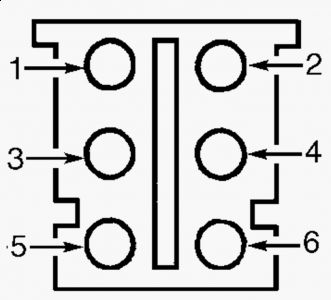
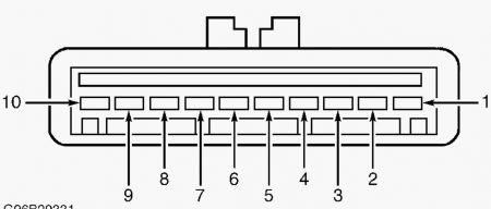
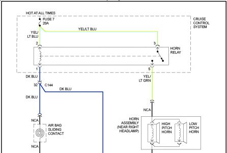
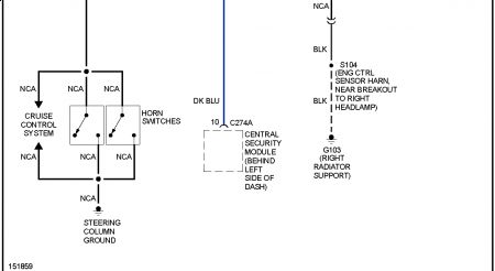
Exam G: HORN INOPERATIVE 1. Disconnect horn relay from battery junction box. Measure voltage between ground and horn relay socket terminals No. i and 3 (both Xanthous/Lite Bluish wires). Encounter Fig. 8 . If battery voltage exists, go to adjacent pace. If battery voltage does not exist, repair open up in Yellow/Light Blue wire betwixt horn relay and battery junction box. See WIRING DIAGRAMS . 2. Check horn relay. Encounter HORN RELAY nether COMPONENT TEST. If horn relay is okay, go to next step. If horn relay is defective, replace horn relay. three. Measure resistance between ground and horn relay socket terminal No. 2 (Dark/Blue wire) while pressing horn switch on steering wheel. Resistance should be 5 ohms or less when horn switch is pressed and greater than 10 k/ohms when released. If resistances are as specified, go to next pace. If either resistance is not as specified, go to step six . 4. Disconnect horn 2-pin harness connector No. C131. Horns are located on right side, behind front bumper. Measure resistance in Yellow/Light Green wire between horn relay socket terminal No. 5 and horn harness connector C131 final No. 1. If resistance is 5 ohms or less, go to next step. If resistance is more than 5 ohms, repair open in Xanthous/Light Light-green wire betwixt horn relay and horn. See WIRING DIAGRAMS . 5. Measure resistance between ground and horn harness connector C131 terminal No. 2 (Black wire). If resistance is v ohms or less, replace horn. If resistance is more than than 5 ohms, repair open in Black wire between horn and ground, Ground is located on correct side of radiator support. See WIRING DIAGRAMS . vi. Deactivate air purse system. See DISABLING & ACTIVATING AIR BAG SYSTEM in AIR Bag RESTRAINT SYSTEMS article in RESTRAINTS. Disconnect horn switch ii-pivot harness connector. Measure resistance between horn switch harness connector terminals. resistance should exist more than than 10 g/ohms when horn switch is released and 5 ohms or less when horn switch is pressed. If resistances are as specified, become to next pace. If resistances are not as specified, replace driver'southward side air bag module. See AIR BAG RESTRAINT SYSTEMS article in RESTRAINTS. seven. Disconnect clockspring half dozen-pivot harness connector C218b. Measure resistance in Dark Blue wire between horn relay socket last No. ii and clock spring harness connector C218b terminal No. 5. See Fig. half dozen . If resistance is 5 ohms or less, become to next step. If resistance is more than 5 ohms, repair open up in Dark Blue wire betwixt horn relay and clockspring. Run across WIRING DIAGRAMS . 8. Remove driver's side air pocketbook and disconnect upper clockspring 5-pin harness connector. Measure resistance in Dark Blue wire between clockspring harness connector final No. 5 and upper clockspring harness connector final No. 3. Measure out resistance in Dark Greenish/Orange wire between clockspring harness connector last No. 3 and upper clockspring harness connector terminal No. 4. See Fig. 6 . If resistances are 5 ohms or less, become to next step. If either resistance is more than than five ohms, supercede clockspring. See CLOCKSPRING under REMOVAL & INSTALLATION. WARNING: Vehicles are equipped with air pocketbook supplemental restraint organization. Earlier attempting Whatsoever repairs involving steering cavalcade, instrument console or related components, see AIR Handbag Rubber PRECAUTIONS and DISABLING & ACTIVATING AIR Handbag Organization in AIR BAG RESTRAINT SYSTEMS article in RESTRAINTS.ix. Disconnect speed control servo/actuator 10-pin harness connector C122. Speed control servo is located on left side of engine compartment. Mensurate resistance in Dark Green/Orange wire between clockspring harness connector concluding No. 3 and speed control servo/actuator harness connector concluding No. 6. See Fig. half-dozen Fig. 7 . If resistance is five ohms or less, go to next footstep. If resistance is more than than v ohms, repair open in Dark Light-green/Orange wire between clockspring and speed command servo/actuator. Run into WIRING DIAGRAMS . 10. Measure resistance betwixt ground and speed control servo/actuator harness connector C122 terminal No. 10 (Black wire). If resistance is 5 ohms or less, replace speed control servo/actuator. See SPEED Control SERVO/ACTUATOR under REMOVAL & INSTALLATION. If resistance is more than than 5 ohms, repair open in Blackness wire between speed control servo/actuator and ground. Ground is located on rear of right front fender. See WIRING DIAGRAMS .
11/24/2009 ...
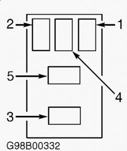
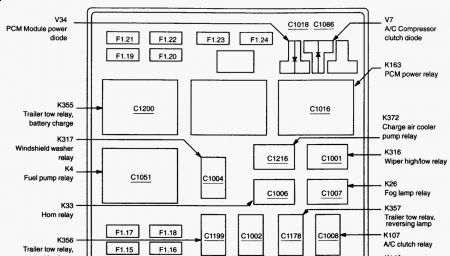
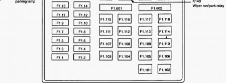
The horn relay is in the battery junction box under the hood, heres the legend:
SPONSORED LINKS
Tuesday, June 18th, 2019 AT 6:37 PM
Source: https://www.2carpros.com/questions/ford-f-150-2002-ford-f150-horn-and-criuse-control

Posting Komentar untuk "Horn Not Working: My Cruise Control and My Horn Quit Working. I ..."